IR Remote Controller For Projection
IR REMOTE CONTROLLER FOR PROJECTION
MEF UNIVERSITY
(MAY 2019)
DESCRIPTION
An IR remote controller sends out pulses of infrared light with transmitter that represent specific binary codes. These binary codes correspond to commands, like power on/off and volume up. The IR receiver in the electronic devices decode the pulses of light into the binary data ( ones and zeroes ) that microprocessor of the device can understand. The microprocessor carries out the corresponding command like on/off . In this project , we are going to do IR remote controller for projection which is in lab. We did turn on/off and voice on/off modes. When we were doing this , we used MPLAB X IDE for programming our PIC and we used Multism program for design our circuit. We used, PIC16F628A, regulator, conductor, resistance (1000 ohm), IR transmitter , IR receiver and crystal (20M ohm). Firstly we generated signal which is 38kHz than we applied it for on/off package code and volume up package code. Then we designed a controller.
THE WORKING PRINCIPLES OF IR REMOTE CONTROLLER
IR lights generally have a 0.75μm to 1000 μm wavelength, so it can not see by humans. Therefore, it is a good idea to chose IR for remote control applications. Moreover, IR light can be emitted easily by LEDs. IR communication becomes easy and cheap. However, light can be blocked by a device or an object, so that there should be always a line of sight between the transmitter and receiver. To overcome this problem, remove the obstacles between the IR transmitter and the receiver. The one of the other problem is noise. Some artificial sources such as light bulbs and heaters also radiate IR waves, which adds up to our information carrying signal, as noise. So the transmitted signal should look different than with noise.
With modulation we make the IR light source turn on and off in a particular frequency. The IR receiver will be sensitive to that frequency, which means will be deaf to any other IR light source turning on/off and volume on/off with a different frequency. That particular frequency, which the receiver and the transmitter agreed on, is called carrier frequency. The carrier frequencies between 36kHz and 46kHz are commonly used in consumer electronics, because there are guides and standards. We cannot use any frequency band we like for any application we use. The most common carrier frequency in remote control devices is 38kHz.
IR COMMUNICATION
The IR communication systems have two point. In our project we used point to point communication.
It requires a line of sight between a transmitter and a receiver without not object and devices between them. Example of this statement is the remote control communication. The other one is diffuse point communication. It doesn’t require any link and line of sight between the transmitter and the receiver is maintained by reflecting or splashing of the transmitted signal by surfaces like roofs and ceilings. Example this statement is the wireless LAN communication system.
IR TRANSMITTER AND IR RECEIVER
IR transmitters shown in Figure 1 and IR receivers shown in Figure 2 are present in many different devices use commonly in consumer electronics. The way of working this tech is that one component flashes an infrared light in a particular pattern can pick up and translate into an instruction. These transmitters and receivers are found in remote controls and all different types of devices, such as televisions, computers. Since infrared remotes are limited to line of sight operation, some products used to extend the signals over a hardwired line transmissions. More of electronic consumer use infrared light for remote controls. They typically generate infrared using LEDs, and the main component of a receiver unit is usually a photodiode. A remote control flashes a pattern of not visible light, which is picked up and then turned into an instruction by the receiver module. The parts necessary to construct transmitter and receivers are typically inexpensive, but these systems are limited to line of sight operation.

Figure 1. An IR Transmitter

Figure 2. An IR Receiver
PIC
The PICs are 18-pin flash-based, high-performance, low -cost, CMOS, fully-static, 8-bit microcontrollers. The PIC have enhanced core features, an eight-level deep stack, and multiple external and internal interrupt sources. The PIC devices have integrated features to reduce external components, thus enhancing system reliability, reducing system cost and reducing power consumption. The PIC series fits in applications ranging from battery chargers to low power remote sensors. The Flash technology customize application programs such as detection levels, pulse generation which extremely fast and convenient. The small footprint packages makes this microcontroller series ideal for all applications with space limitations.
ON/OFF CODE
NEC protocol for remote control:
•8 bit address and 8 bit command length.
•Address and command are transmitted twice for reliability.
•Pulse width modulation.
•Bit time of 1.125ms or 2.25ms.
On/off code of projection shown in Figure 3 and logical 1's and 0's for on/off code shown in Figure 4.

Figure 3. On/off code of projection

Figure 4. Logical 1's and 0's for on/off code
Send logical '1': In 2.25 msecduration 560 sec pulse and blank in the rest.
Send logical '0': In 1.12 msecduration 560 sec pulse and blank in the rest.
BLOCK DIAGRAM
The block diagram of IR Transmitter and regulator circuit shown in Figure 5. Circuit of IR Transmitter and regulator shown Figure 6.

Figure 5. Block diagram of of IR Transmitter and regulator circuit

Figure 6. Circuit of block diagram
The materiasl which were used in design:
- IR Receiver
- IR Transmitter
- 1k ohm resistor
- 20 mhz crystal
- PIC
- Regulator
- 2xCapacitor
- 9 volt battery
CODE IN PIC
/* * File: main.c
* Author: EELab
*
* Created on February 27, 2019, 1:19 PM
*/
#define _XTAL_FREQ 20000000
// PIC16F628A Configuration Bit Settings
// 'C' source line config statements
// CONFIG #pragma config FOSC = HS
// Oscillator Selection bits (INTOSC oscillator: CLKOUT function on RA6/OSC2/CLKOUT pin, I/O function on RA7/OSC1/CLKIN)
#pragma config WDTE = OFF // Watchdog Timer Enable bit (WDT disabled)
#pragma config PWRTE = ON // Power-up Timer Enable bit (PWRT disabled)
#pragma config MCLRE = OFF // RA5/MCLR/VPP Pin Function Select bit (RA5/MCLR/VPP pin function is digital input, MCLR internally tied to VDD)
#pragma config BOREN = ON // Brown-out Detect Enable bit (BOD disabled)
#pragma config LVP = OFF // Low-Voltage Programming Enable bit (RB4/PGM pin has digital I/O function, HV on MCLR must be used for programming)
#pragma config CPD = OFF // Data EE Memory Code Protection bit (Data memory code protection off)
#pragma config CP = OFF // Flash Program Memory Code Protection bit (Code protection off)
// #pragma config statements should precede project file includes.
// Use project enums instead of #define for ON and OFF.
#include <pic16F628A.h>
#include <xc.h>
void main(void) {
TRISA=0xFF; // select inputs and outputs.
TRISB1=0x00; int i; int on_off[] ={0,0,0,0,1,1,0,0,1,1,1,1,0,0,1,1,0,0,0,1,1,0,0,0,1,1,1,0,0,1,1,1}; //our on off signals
// int volume_up[] = {,,,,,,,,,,,,,,,,,,,,,,,,,,,,,,,}; //we cannot find datas of volume up and down.
// int volume_down[] ={,,,,,,,,,,,,,,,,,,,,,,,,,,,,,,,};
while(1){ // this loop for sending signal infinitely if(RA0==1){
if input RA0=0, we send on off signals
for(i=0; i<32; i++){
PORTB=0b00000010; //we add small delay.
__delay_ms(10);
PORTB=0b00000000;
__delay_ms(10);
if(on_off[i]==1){ // if next value of on_off array is “1”, we are sending specific signal of 1
for(i=0; i<20; i++){
PORTB=0b00000010;
__delay_ms(0.011785);
PORTB=0b00000000;
__delay_ms(0.011785); }
PORTB=0b00000000;
__delay_ms(1.69); }
else{ //else, we are sending specific signal of 0
for(i=0; i<20; i++){
PORTB=0b00000010;
__delay_ms(0.011785); PORTB=0b00000000;
__delay_ms(0.011785); } PORTB=0b00000000;
__delay_ms(0.56); } } }
//VOLUME ON
if(RA1==1){
PORTB=0b00000010; //we add small delay.
__delay_ms(10);
PORTB=0b00000000;
__delay_ms(10);
for(i=0; i<32; i++){
if(on_off[i]==1){
for(i=0; i<20; i++){
PORTB=0b00000010;
__delay_ms(0.011785);
PORTB=0b00000000;
__delay_ms(0.011785); }
PORTB=0b00000000;
__delay_ms(1.69); }
else{
for(i=0; i<20; i++){
PORTB=0b00000010;
__delay_ms(0.011785);
PORTB=0b00000000;
__delay_ms(0.011785); }
PORTB=0b00000000;
__delay_ms(0.69); } } }
//VOLUME OFF
if(RA2==1){
for(i=0; i<32; i++){
if(on_off[i]==1){
for(i=0; i<20; i++){
PORTB=0b00000010;
__delay_ms(0.011785);
PORTB=0b00000000;
__delay_ms(0.011785); }
PORTB=0b00000000;
__delay_ms(1.69); }
else{
for(i=0; i<20; i++){
PORTB=0b00000010;
__delay_ms(0.011785);
PORTB=0b00000000;
__delay_ms(0.011785); }
PORTB=0b00000000;
__delay_ms(0.69); } } } }
FLOW CHART OF CODE
The flow chart of code shown in Figure 7.
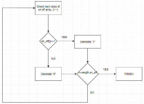
Figure 7. Flow chart of code
RESULTS
On the digital oscilloscope our generated signal is yellow, and signal that receiver gave is blue. If transmitter signal has 1, receiver set it 0, otherwise receiver set it 1. That shown in Figure 8. 38kHz during 560 us shown in Figure 9. Duration of sending “0” signal is 1.68 ms. That shown in Figure 10.

Figure 8

Figure 9

Figure 10
TASKS
1-Write code to generate 38 kHZ signal
2-Generate 38 kHZ signal with crystal
3-Write the control program for on-off switch
4-Write code to change voice for projection
5-Complete circuit
6-Design a control panel
SUMMARY AND CONCLUSION
First we generated signal on MPLAB. For generating signal, we did calculation for our delay time and loops limit. We loaded it on PIC. After that, we designed our signal on Logism and we setup it on breadboard. We use regulator circuit for converting 9V to 5V. We did not send our signal to projection.
In this project, we learned how to generate signal with using C programming language, how to calculate spesific values of signal for C. We experienced long-term team project and we saw its challenges. The most challenging thing is generating 38 khz package code for projection. The calculating of delay times were hard for us.
REFERENCES
Morkel R.,(October 15, 2015),'' How do an IR transmitter and receiver work?''
https://www.quora.com/How-do-an-IR-transmitter-and-receiver-work
Agarval T.,(October 6, 2014),'' Sub-GHz Wireless Communication with Transmitter and Transceivers''
https://www.efxkits.co.uk/sub-ghz-wireless-communications/
https://www.sbprojects.net/knowledge/ir/


Comments
Post a Comment